
Design Guidelines & DFM Rules for Custom Part Manufacturing
Precision Parts. Endless Possibilities.
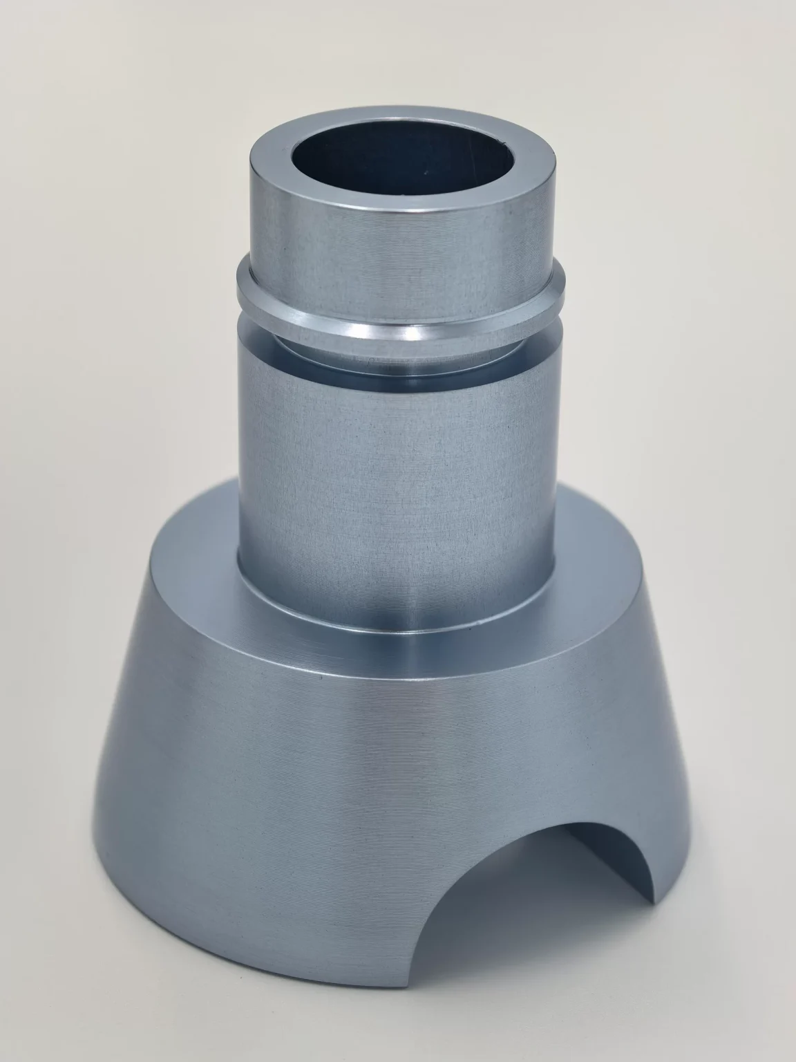
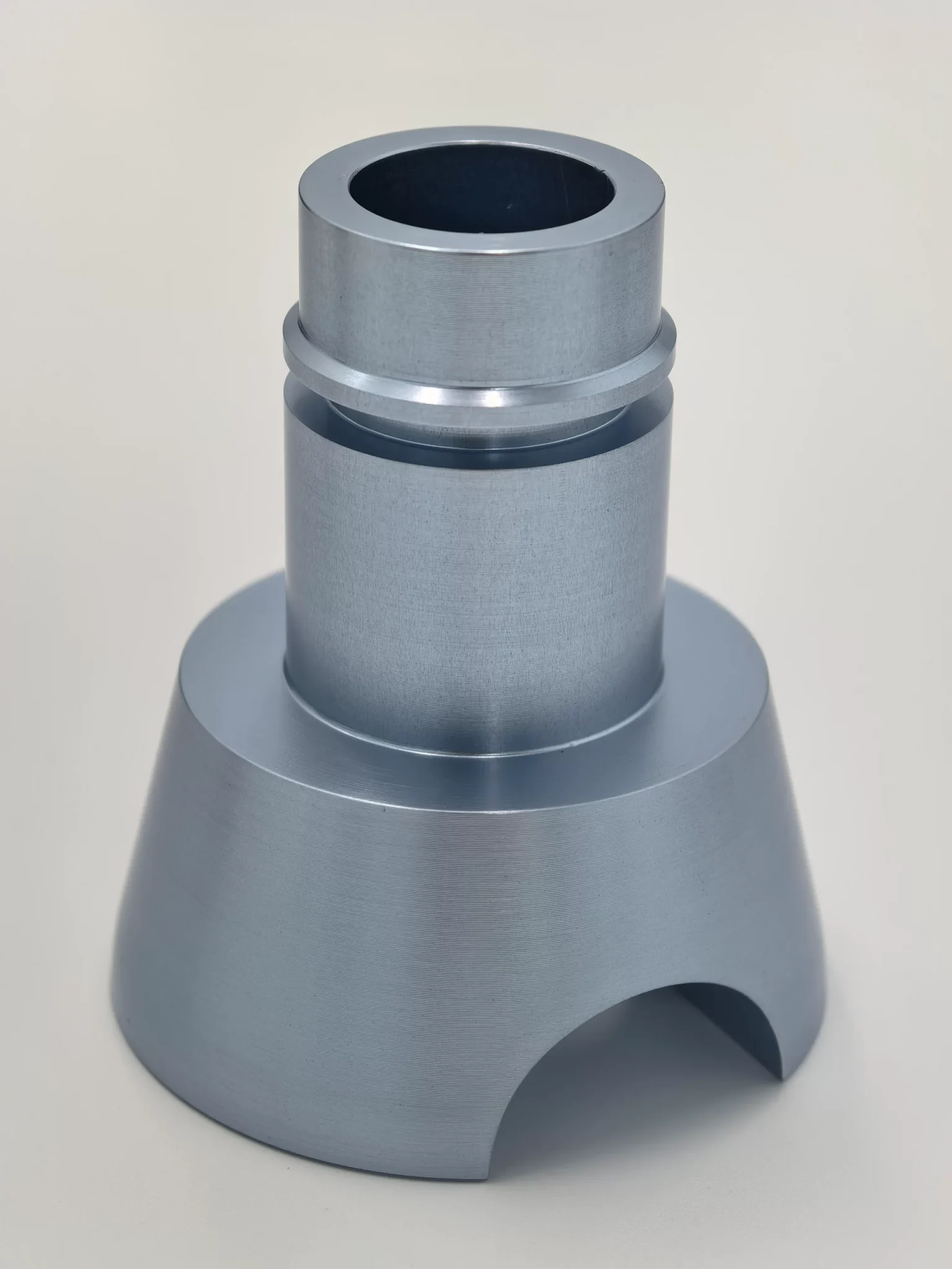
Explore our custom manufacturing capabilities through real product examples.
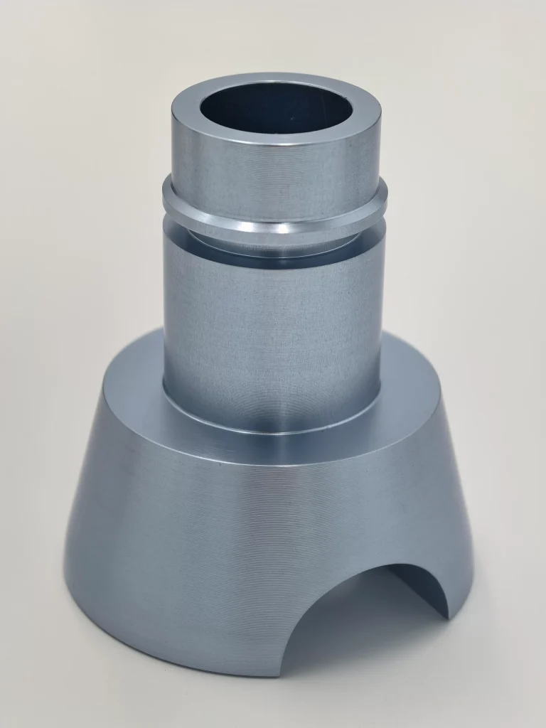
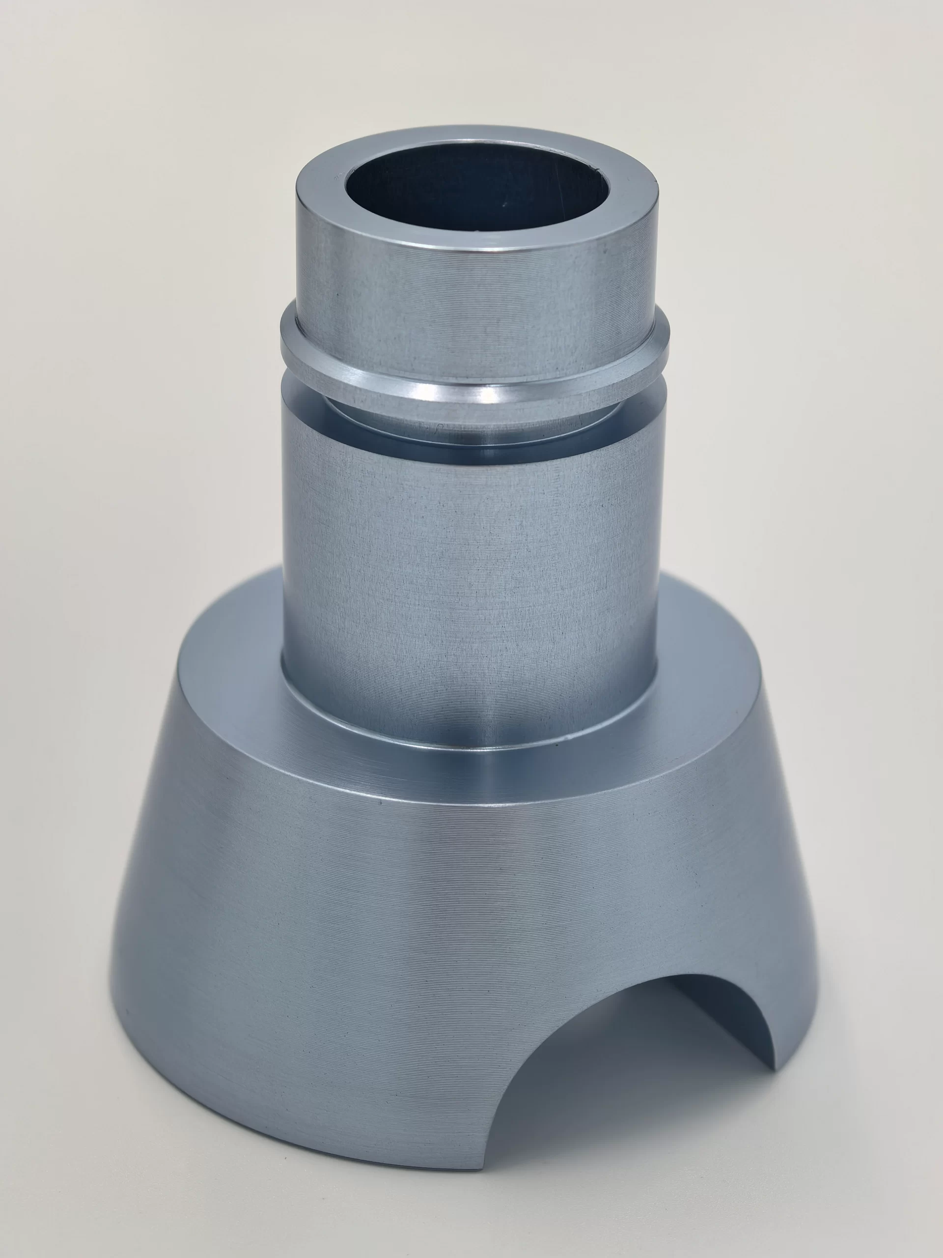
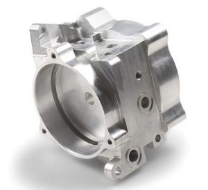

Browse guidelines by process
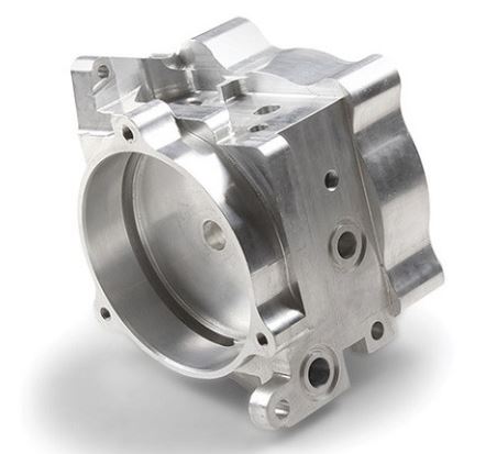
CNC Machining
Tool access, internal radii, thread callouts and the tolerances worth paying for.
Sheet Metal Fabrication
Bend radii, hole-to-bend distance, hems, notches and grain direction.
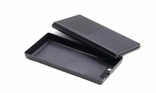
Injection Molding
Draft angles, wall uniformity, ribs, bosses, snap fits and gate placement.
Die Casting
Draft, parting line, as-cast radii, and which features need post-machining.
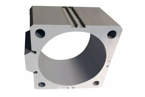
Aluminum Extrusion
Extrusion circle, uniform wall, tongue ratios and joint design.
3D Printing / Additive
Min feature size, overhang angles, support strategy and anisotropy.
Surface Finishing
Which finish to call out, where Ra matters, and what hides tool marks.
Cutting & Profiling
Laser, waterjet and plasma: kerf, minimum hole size, nesting margins.
Or start from the feature you are stuck on
The standard, and what we hold
| Nominal size (mm) | f — fine | m — medium | c — coarse |
|---|---|---|---|
| 0.5 – 3 | ±0.05 | ±0.1 | ±0.2 |
| over 3 – 6 | ±0.05 | ±0.1 | ±0.3 |
| over 6 – 30 | ±0.1 | ±0.2 | ±0.5 |
| over 30 – 120 | ±0.15 | ±0.3 | ±0.8 |
| over 120 – 400 | ±0.2 | ±0.5 | ±1.2 |
| over 400 – 1000 | ±0.3 | ±0.8 | ±2.0 |
| over 1000 – 2000 | ±0.5 | ±1.2 | ±3.0 |
| over 2000 – 4000 | — | ±2.0 | ±4.0 |
Class v (very coarse) is omitted: it is written for raw castings and flame-cut blanks, not for the processes quoted here. Below 0.5 mm the standard requires an individually stated tolerance.
| Shorter leg (mm) | f — fine | m — medium | c — coarse |
|---|---|---|---|
| up to 10 | ±1° | ±1° | ±1°30′ |
| over 10 – 50 | ±0°30′ | ±0°30′ | ±1° |
| over 50 – 120 | ±0°20′ | ±0°20′ | ±0°30′ |
| over 120 – 400 | ±0°10′ | ±0°10′ | ±0°15′ |
| over 400 | ±0°5′ | ±0°5′ | ±0°10′ |
| Nominal size (mm) | f & m | c & v |
|---|---|---|
| 0.5 – 3 | ±0.2 | ±0.4 |
| over 3 – 6 | ±0.5 | ±1.0 |
| over 6 | ±1.0 | ±2.0 |
| Property | What we state | Source |
|---|---|---|
| General tolerance — metals | ISO 2768-fH (fine) | Standards page |
| General tolerance — plastics | ISO 2768-mK (medium) | Standards page |
| Thread class — metric | ISO 965-1, 6H internal / 6g external | Standards page |
| Deburring | Sharp edges chamfered 0.25 ± 0.125 mm | Standards page |
| Tightest linear tolerance | ±0.005 mm (±0.0002 in) on a marked feature | Standards page |
| Minimum feature size | 0.5 mm or Ø 0.50 mm | Standards page |
| Minimum wall thickness | 0.8 mm metals / 1.5 mm plastics | Standards page |
Every row above is published on our Standards page. They are our own working limits rather than an ISO class, and the two pages are kept in step — if a value moves on one, it moves on the other in the same release.
| Thread | Pitch | Minor dia. (6H) | Typical use |
|---|---|---|---|
| M2 × 0.40 | 0.40 mm | 1.567 – 1.679 mm | Electronics, small enclosures |
| M3 × 0.50 | 0.50 mm | 2.459 – 2.599 mm | Most common machine thread |
| M4 × 0.70 | 0.70 mm | 3.242 – 3.422 mm | General assembly |
| M5 × 0.80 | 0.80 mm | 4.134 – 4.334 mm | Panel and frame joints |
| M6 × 1.00 | 1.00 mm | 4.917 – 5.153 mm | Structural fastening |
| M8 × 1.25 | 1.25 mm | 6.647 – 6.912 mm | Heavy brackets, bases |
| Thread | TPI | Class | Tap drill |
|---|---|---|---|
| 4-40 | 40 | 2B | #43 – 0.0890 in |
| 6-32 | 32 | 2B | #36 – 0.1065 in |
| 8-32 | 32 | 2B | #29 – 0.1360 in |
| 10-24 | 24 | 2B | #25 – 0.1495 in |
| 10-32 | 32 | 2B | #21 – 0.1590 in |
| 1/4-20 | 20 | 2B | #7 – 0.2010 in |
If your drawing specifies a thread class, we hold what you specify. UNC and UNF follow ASME B1.1 (2A external / 2B internal); NPT follows ANSI/ASME B1.20.1. NPS, NPTF, STI and BSP are available on request; ACME is not.
Browse guidelines by material
Aluminum alloys
Stainless steel
Carbon & alloy steel
Copper & brass
Engineering plastics
High-temp & specialty
Run the DFM check before you send us the file
Mark the feature and its position on the drawing. When the title block is silent we apply ISO 2768-fH for metals; the tightest we hold on a marked feature is ±0.005 mm.
Prolean capability
Measured as nominal wall on the section. Capability minimum 0.8 mm in metals; thin walls deflect under cutting force, so they add passes and cost.
Prolean capability
Compare the pocket corner radius with the cutter radius you are implicitly asking for. A radius of at least one third of the pocket depth keeps the cutter rigid.
Recommended design value
Basis is depth ÷ cutter diameter. Up to about 4:1 is routine; beyond that we need long-reach tooling, which means more passes, more deflection and a higher price.
Industry reference
Our default is ISO 965-1, 6H internal / 6g external. A callout of “M6” alone leaves the thread class open, and the class is what the gauge checks.
Prolean capability
Basis is the inside radius, not the outside. As a starting rule R ≥ 1 × t; harder and high-strength alloys need more before they crack.
Industry reference
Measured from the hole edge to the bend tangent — the point where the radius starts. Not centre-to-centre, and not to the bend centreline. Starting point: ≥ 2.5 × t.
Industry reference
Basis is the narrowest width against material thickness. Notch width at least 1.5 × t; tabs at least as wide as the material, or they tear.
Industry reference
Basis is the bend line relative to the rolling direction. Bending across the grain cracks at much larger radii than bending with it, so the layout of the flat pattern matters.
Recommended design value
Give formed dimensions, bend angles, inner radii and bend direction for every bend. A dimensioned flat pattern alone does not define bend sequence or springback.
Recommended design value
Basis is nominal wall. Capability minimum 1.5 mm in plastics. Thick-to-thin transitions should be gradual — a step change sinks on the thick side.
Prolean capability
Basis is angle against draw depth, matched to the finish: 0.5° minimum on smooth vertical faces and roughly 1° per 25 mm of depth; 3° for light matte textures; 5° or more for medium and coarse textures.
Industry reference
Basis is rib thickness against nominal wall. Rib at 0.5–0.6 × wall, height no more than 3 × wall, radiused at the base. A rib as thick as the wall sinks.
Recommended design value
Basis is boss wall against nominal wall. Boss wall around 0.6 × wall; a sharp base concentrates stress and creates a sink mark opposite it.
Recommended design value
Basis is whether the feature can release on the draw axis. An undeclared undercut is found at tooling, when it is expensive to fix.
Recommended design value
Answered 0 of 15 · confirmed 0 · not applicable 0 · need help on 0
Upload it with your RFQ — the DFM review is included at no cost, and an engineer tells you which items above actually apply to your part.
Recommended design guides
Questions engineers ask us at this stage
What drawing formats do you accept?
Native and neutral CAD: STEP, IGES, X_T, SLDPRT, SLDASM, IPT and STL. Pair the 3D model with a 2D PDF that carries your GD&T — for anything with a real tolerance callout, the PDF is what we inspect against.
Do I have to pay for a DFM review?
No. Every quote includes a manufacturability review by an engineer. We flag the features that will drive cost or cause a problem, and suggest a change if one exists — before you commit to an order.
Which tolerance class do you apply if my drawing is silent?
We apply the ISO 2768 general-tolerance default for the material: fH (fine) for metals and mK (medium) for plastics, consistent with our Standards page. The class we used is stated on the inspection documentation. If a dimension needs to be tighter, mark the feature and its position on the drawing rather than tightening the whole title block — we confirm the achievable tolerance on that feature in the quote.
What is the minimum order quantity?
It depends on the process, because tooling does. For CNC machining, sheet metal and 3D printing there is no tooling, so one part is a normal order and prototyping is part of our regular workload. For injection molding, die casting and extrusion a mould or die is required, so the economic minimum is set by that tooling — we quote the tooling and the part price together so you can see where the break-even sits.
How do I choose a surface finish?
Start from the substrate and the function, not from appearance. Anodizing applies to aluminium only; powder coating suits steel and aluminium but adds build-up, which is a problem on tight-tolerance mating faces; passivation is for stainless; black oxide is for steel. Tell us the substrate and what the surface has to do — corrosion, wear, conductivity, appearance — and we will narrow it to the finishes that actually fit. Our surface finish guide compares cost and lead time for each option.
Can you work from a 2D drawing only?
Yes for flat, 2D-profiled parts — laser, waterjet and simple blanking work from a dimensioned flat pattern. For anything that is formed or bent, send the formed dimensions, bend angles, inner radii and bend direction for each bend. A flat pattern alone does not define the bend sequence or how the material will spring back, and we would be guessing at the finished part. For machined 3D geometry, send the model.
Still not sure the design is manufacturable? Send us the file.
Latest Blog
Check out our latest blogs, we share industry trends, design tips, and experience earned from manufacturing.
- Electroplating Vs Electro-less plating
- What are the types of surface finishes for CNC machining?
- Common Materials for CNC Machining
- Tolerances in CNC Machining
- Sheet Metal Fabrication: Enclosures for Electronics
- Best Cutting Tools for CNC Machining– Choose the Right
- An Ultimate Guide to CNC Copper Machining
- Production Cycle Time in CNC Machining
- Electroplating Vs Electro-less plating
- What are the types of surface finishes for CNC machining?
- Common Materials for CNC Machining
- Tolerances in CNC Machining
- Sheet Metal Fabrication: Enclosures for Electronics
- Best Cutting Tools for CNC Machining– Choose the Right
- An Ultimate Guide to CNC Copper Machining
- Production Cycle Time in CNC Machining

Die Cast Industry: Status in 2026 and Trends by Segments
Die-casting is a process of creating metal components by forcing molten material into a reusable mold (called a die), where it fills the cavity and takes the shape upon solidification.
Read more →
Electric Discharge Machining Applications Across Industries
Electrical Discharge Machining (EDM) is a non-conventional subtractive manufacturing process, in which a tool (electrode/wire) removes the material from conductive workpieces using controlled electric sparks inside a dielectric medium
Read more →
PEI CNC Machining: Material Grades, Processes, and Considerations
PEI CNC machining converts raw PEI rod, bar, or plate into functional components using cutting, milling, turning, drilling, and other suitable operations using the CAD model & CNC program.
Read more →DESIGN-FOR-MANUFACTURE
Make intent measurable before the drawing reaches production
A robust DFM review translates functional intent into dimensions, datums, materials and inspection methods. It identifies which features must be controlled and which can be released to an agreed general tolerance class.
Engineering data to lock before release
| Datums | Functional locating surfaces and assembly references |
|---|---|
| Tolerance scheme | Individually controlled versus general tolerances |
| Surface callout | Texture parameter, unit and functional area |
| Inspection path | Gauge, CMM, visual standard or test method |
A callout should specify the functional requirement; adding a number without a datum or test context can create conflicting inspection results.
